While a good oil analysis report provides detailed analyses and actionable recommendations, it is still important for your organization to have someone who can perform oil analysis interpretation in the context of the actual machine environment. Below are some fundamental tips on how to interpret your reports.
Understanding Oil Analysis Reports
In our last article on Simple Guide for Oil Analysis Interpretation, we mentioned the deductive approach and inductive approach when going through an oil analysis report. When using the deductive approach, you can start reading the analyses and interpretations before going through each oil analysis parameter while with the inductive approach, you do the opposite.
To help you get organized with your reports, start by separating the reports based on the rating system which tells you the level of criticality (normal, caution, warning). When you see that a report indicates a warning condition, check which aspect of oil analysis contributed to this condition: oil condition, contamination condition, or machine wear condition.
Oil Condition
A. Viscosity Result Interpretation
Considered as the most important property of lubricants, viscosity is one of the parameters that need to be monitored regularly. Viscosity is defined as a lubricant’s capacity to resist flow at a given temperature. When a lubricant does not possess the right viscosity, the lubricant will not be able to create enough film that is needed to lessen metal-to-metal contact, carry away contamination, and transfer heat properly. A lubricant with the wrong viscosity can inadvertently lead to overheating, accelerated wear, and machine failure.
We test and measure the viscosity of industrial oils at 40 degrees Celsius. These industrial oils are used in applications such as turbine and hydraulic equipment. Meanwhile, engine oils are tested at 100 degrees Celsius. To be categorized at a specific ISO VG (viscosity grade), the oil’s viscosity must fall within the acceptable interval which is ± 10% of the grade. Take for example, for an oil to be classified as ISO VG 22, its viscosity must fall between 19.8 and 24.2. This means that the viscosity of the oil is within the normal range. If the oil’s viscosity falls outside of ± 10% and less than ± 20%, the viscosity can be considered at a caution level. When the oil’s viscosity falls outside ± 20%, the oil’s viscosity grade is at a critical level.
B. Determining Acid Number
Acid Number (AN) is another parameter that is used to determine the condition of the oil. It helps monitor the level of acid buildup which also relates to oil oxidation. When there’s a high amount of acid, it means that your lubricant undergoes excessive oxidation or additive depletion which could lead to corrosion. Acid number (AN) is determined through a laboratory process called titration. We use the standard unit mg KOH/g to report AN. Determining the critical level of AN depends on the equipment and application.
AN measures both weak organic acids and strong inorganic acids. When acid contaminants or wrong oil is present or when additives get depleted and oxidation by-products increase, so too acid concentration. There are cases, however, when an acid number can give a false-positive or false-negative result. Some additives are mildly acidic which can give higher AN. When these additives get depleted, the AN decreases. Thus, it is important to not only look at acid number by itself but to consider other factors such as additive health and water content.
Contamination Condition
A. Measuring Moisture Content
The presence of water is a serious threat to the equipment as it promotes corrosion of components and oxidation of the oil. Water can also reduce the load-handling capacity of oil, separates additive from the oil, and if not addressed, can lead to catastrophic failure.
The most common laboratory test that is used to measure water is the Karl Fischer coulometric method. Most systems require that water should not exceed 500 parts per million (1 ppm = 0.00001% by volume). When the level of moisture is abnormally high, it indicates a source of water ingress. Check your breathers, seals, reservoir covers, heat exchangers or water jackets, and the condition of condensation.
B. Gauging Particle Counts
Another key parameter that you have to monitor is the particle count. Particles, big or small, tend to cause serious damage when they enter the system. Particle count, as the name suggests, counts the particles according to particle size. The current standard for reporting cleanliness is ISO 4406:99. Before you measure particle count, it is important to set your particle count target. When the actual particle count is higher than your cleanliness target, that means your system is dirty and you need to install your corrective actions as soon as possible.
Due to the straightforward characteristic of particle count, most maintenance professionals rely on particle count. Nowadays, online sensors and onsite particle counters have become increasingly popular. While oil cleanliness is vital to the health of equipment, it is not the be-all and end-all parameter. Relying on particle count alone will leave you blind from the effects of abnormal oil conditions and machine wear conditions. It cannot distinguish varnish, demulsibility, acidity, or wrong oil contamination. Therefore, it is still very important to gather information using other parameters.
Machine Wear Condition
A. Elemental Spectroscopy
Particle count is a powerful parameter but it does not tell you the nature of contaminant present in your system. With elemental analysis, which is sometimes called elemental spectroscopy, you will have an idea of whether the particles are machine wear metals, foreign contaminants, or additive elements. One particle application of elemental spectroscopy is to determine whether there is a mixing of different oils or change in the formulation.
Elemental analysis uses the principle of atomic emission spectroscopy (AES) to determine different types of elements. In AES, samples are excited using a high-energy source which in turn excites atoms. When atoms get excited, they go to a higher electronic state but revert to a lower state by losing this energy. This energy is emitted in the form of light which is inversely proportional to wavelength. Because atoms have different electronic structures, they will exhibit varying degrees of energy absorption and emission which we can use to determine the types of elements and their concentration.
Oil analysis laboratories typically use one of the two types of atomic emission spectrometer: the rotating disk electrode (RDE) or inductive coupled plasma (ICP) instrument. With ICP, only particles smaller than 3 microns can be measured while RDE can measure smaller than 8 or 10 microns. With this limitation, it can be problematic to detect larger wear particles caused by fatigue issues from rolling elements, severe sliding wear, spalling, and cutting wear. To address this, one complementary technique that can be used to measure larger particles is Rotrode Filter Spectroscopy (RFS). With RDE and RFS together, you can get a clearer picture of what is happening in your machine.
B. Analytical Ferrography
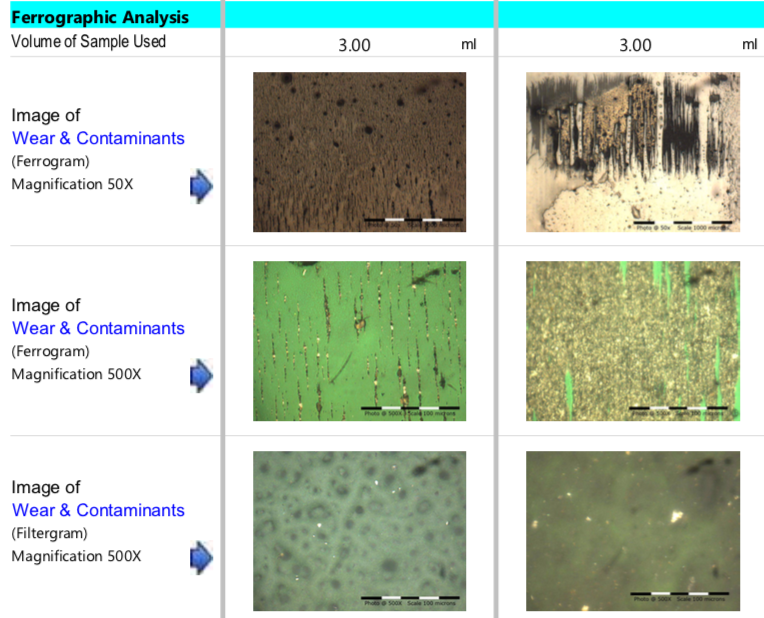
Analytical ferrography is one of the most powerful oil and machine diagnostic tools today. It can be used to identify an active wear problem and failure modes. Analytical ferrography is oftentimes not included in a basic oil analysis package due to the high price and lack of understanding of its full value. Analytical ferrography results include a photomicrograph of the wear debris along with specific descriptions of the particles such as size, shape, and metallurgy. Using analytical ferrography, you can draw conclusions regarding the wear rate and health of the component.

Source: machinerylubrication.com


