


Anyone who has benefitted from the advancements in ultrasound testing will agree that this technology is no longer for leak testing. It works with vibration analysis, infrared imaging, motor-circuit testing, and oil analysis.
Others argue that the core of every predictive maintenance program should be ultrasound, owing to its flexibility, cheap cost, and ease of implementation.
Safety should be taken very seriously. Inspector training is about security as much as it is about the procedure. Ignoring the additional risk of working in a noisy compressor room without appropriate safety equipment is also tricky.
For more than 20 years, ultrasound has provided early warning signals for mechanical failure. You are too late if you can hear compressor valves knocking with a screwdriver. But, there is a fundamental difference in philosophy between what ultrasound inspection proposes to do and what is hoped to be achieved with a screwdriver. Ultrasound monitors the condition of that compressor valve from when it is new until it is ready to be replaced while providing feedback about subtle changes in its operational state. The screwdriver approach is employed "to discover the cause of the problem," implying that the banging is audible to the human ear and that the compressor would fail in days, hours, or minutes.
Advanced Valve Testing
The ability of ultrasound to record dynamic wave files on reciprocating compressors is a considerable advantage. Extending 1/10th or even 1/100th of a second of data using essential time waveform analysis tools to witness a valve open, exhaust, and close is trivial. During that blink of an eye, you may determine if the valve seat is wholly sealed and even assess the strength of the valve spring. This data can be printed in an analytical report, which serves as a summary for management to decide if further action is necessary. Because the record will be archived in the future, the next decision will have a foundation for comparison.
One or more cylinders in a reciprocating compressor compress gases. Within the cylinder, pistons rotate up and down. New gas is taken into the cylinder through an intake valve on the downstroke. The trapped gas in the cylinder is compressed and pushed via an output valve to a receiver or tank on the upstroke. More strong valves with springs are used in more complicated reciprocating compressors.
Opportunities for failure are many. The integrity of the seals surrounding the piston cylinder wall lowers compression efficiency. Dirty and worn valves do not seat due to corrosion and buildup around the valve head. Internal leakage around the piston and valve head can be discovered via ultrasound examination by capturing and analyzing a dynamic ultrasound signal over time. Early mechanical failures, which can lead to screwdriver-detectable valve-knocking, can be seen this way, too.
High amplitude signals between the valve impacts can reveal mechanical looseness or internal leakage from piston rings or the valve seat. Comparable valves can be compared by scaling the time signal's Y-axis and displaying it in an overlay or side-by-side manner.
A documented report that cites the historical evolution of your compressor's health can be a unique and professional way to present your data. It is an effective tool for informing maintenance managers when an issue worsens, and that immediate action is necessary.
There is no substitution for walking the plant floor and taking account of the state of affairs. Talking with operators may teach you a lot. Operators have the best pulse for machine conditions because they work around them daily. For those ready to take the next, getting to know the expectations of operations, management, and front-line staff is the best approach. From that point, defining the assets that need the most critical monitoring will be as crucial as figuring out which technologies should be used to collect the data.
Documentation is the final piece of the puzzle. With it, all other initiatives are worthwhile. Contemporary data collection procedures that can be trended and reported on are preferable over antiquated approaches that rely on individual interpretation and old-school gimmicks.
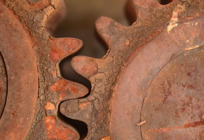
Determining the Root Cause of Gear Failure
Several circumstances might contribute to an unanticipated increase in gear failures. Begin by looking into what has changed since the failures increased.
A post-failure oil analysis investigation on gears is recommended. Among the tests, you should perform elemental analysis and analytical ferrography. These two tests can give valuable insight into the fundamental cause of the failures. The elemental analysis will explain which contaminant induces the failure and which metals are being worn. Analytical ferrography can help state which type of wear is being produced.
 Source: Noria
Abrasive wear will appear as metal particles with curls, spirals, or loops, while adhesive wear usually can be seen as more giant platelets or chunks with striations or tempered coloring. Surface fatigue wear will often appear as flat plates with jagged edges. The size of these particles can state the severity. The greater their size, the more severe the wear. Corrosive wear will resemble fine particles that are too small to distinguish.
Also, inspect the gearing and internal gearbox surfaces. Pinpoint where on the gear tooth the wear is occurring to understand better which types of particles you should look for in the analytical ferrography tests. If there is excessive wear on the pitch line, there should be greater surface fatigue wear because this is where rolling friction occurs. You should find more abrasive and adhesive wear particles if more wear is above or below the pitch line.
Finally, review the procedures for maintaining your equipment. There is always the chance that someone has deviated from best practices and introduced contamination.
After you understand what is going on inside the gearbox that is causing the failures, you can examine and discover where the contaminants are entering the system and then remove the ingression points to restore dependability.
Steps
Before determining the cause of gear failures, you must go over specific steps to determine the cause better.
Step 1. Preparing for Inspection
Before arriving, interview a contact person at the failure site and describe what you need to check the gearbox, including people, equipment, and working conditions. Suggest that an experienced technician dismantle the device under your supervision. But ensure work is done on the gearbox once you arrive. This means no cleaning. Otherwise, a well-meaning technician could destroy evidence.
Step 2. Failure Inspection
Review the background information and service history with the contact person before beginning the inspection. Then interview those involved in the gearbox's design, installation, operation, maintenance, and failure. Encourage them to tell everything they know about the gearbox, even if they feel it is unnecessary.
Step 3. Determine the Type of Failure
Now it's time to examine the information and determine how the gear failed. This is where our earlier discussion on determining the cause of gear failures becomes relevant.
Step 4. Form and Test Conclusions
When all computations and testing have been performed, you must develop one or more hypotheses about the likely reason for failure and then decide whether the data supports or refutes the hypothesis. The results of this evaluation may make it necessary to change or abandon the initial hypotheses. Or pursue new lines of investigation.
Step 5. Reporting Results
Finally, the last step is to report the results. A failure analysis report should include all essential information discovered during the investigation, inspections and testing, evidence weighing, findings, and suggestions. Present the data in tables or figures. Good photos are beneficial for portraying failure characteristics.
Training
CRE Philippines offers various training as we want to “empower industries to increase uptime.” Our most recent upcoming training is Vibration Analysis II from March 20 to 24, 2023, and Machinery Lubrication from April 26 to 28, 2023. Contact us at CRE Philippines to learn more.
Sources:
Errichello, B., & Muller, J. (n.d.). How to Analyze Gear Failures. MachineryLubrication. Retrieved from https://www.machinerylubrication.com/Read/150/gear-failures
Lubricants Testing. Element. (n.d.). Retrieved from https://www.element.com/materials-testing-services/fuels-and-lubricants/condition-monitoring-by-oil-analysis
Noria Corporation. (n.d.). Guidelines for Determining the Cause of Gear Failures. MachineryLubrication. Retrieved from https://www.machinerylubrication.com/Read/31226/gear-failure-causes
Rienstra, A. (n.d.). Inspecting Reciprocating Compressors with Ultrasound. ReliablePlant. Retrieved from https://www.reliableplant.com/Read/29745/reciprocating-compressors-ultrasound